Call us 24/7+91-9867228252
PAVAN ELECTRO SOURCE: โ€œEmpowering Innovation Through Electronics, Education & Technologyโ€
Call us 24/7+91-9867228252

ESP8266 WiFi Air Mouse โ€“ Control Devices with Hand Gestures

๐Ÿ” Project Overview

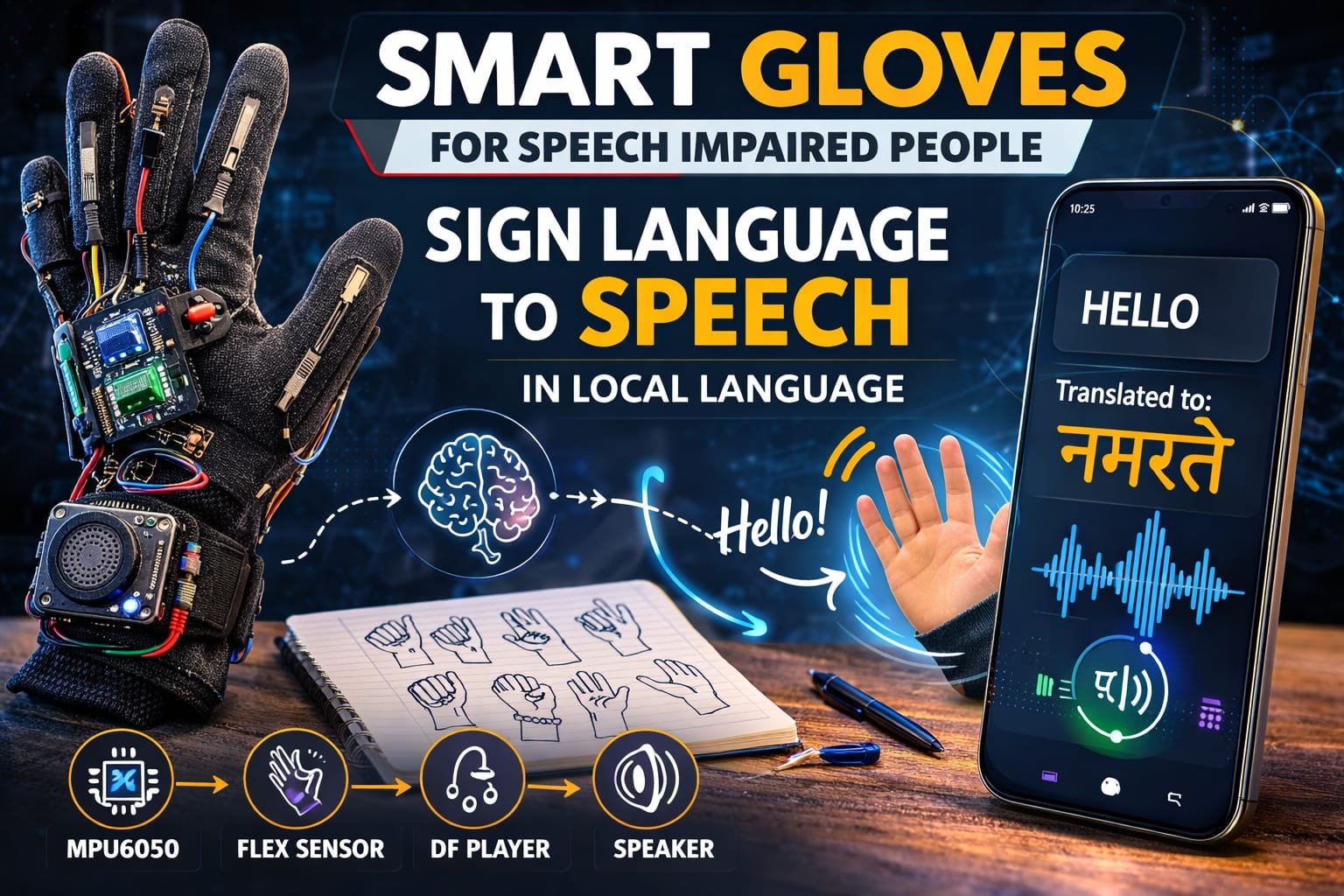
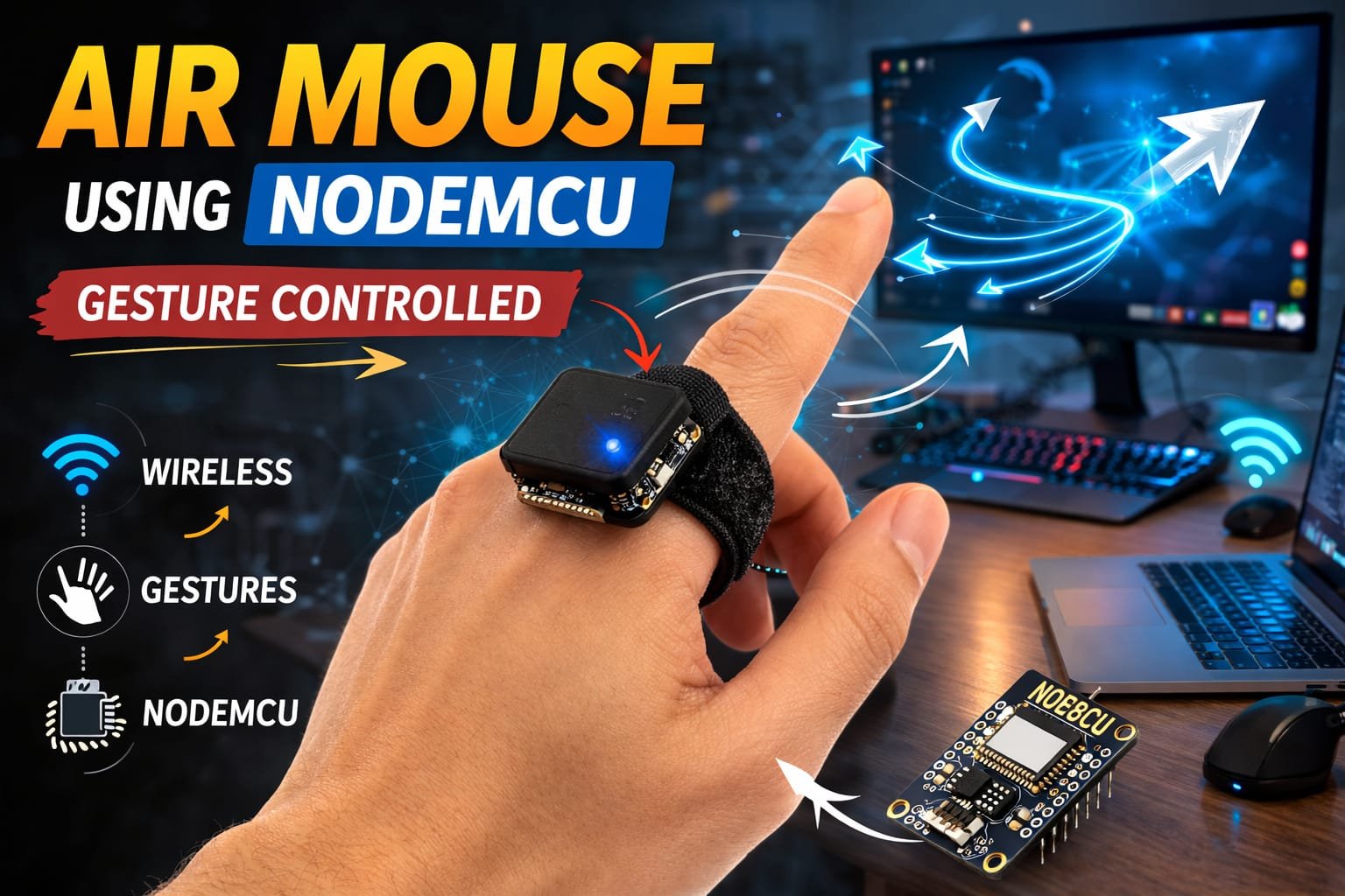
This project is an Air Mouse system that allows users to control a computer or smart device wirelessly using hand gestures. The system uses an MPU6050 motion sensor to detect hand movement and orientation. The ESP8266 (NodeMCU) connects via WiFi to send gesture commands to a computer or web-based interface.

When a user moves or tilts their hand, the sensor data is transmitted to the ESP8266, which interprets the gestures and controls the cursor movement, clicks, or scrolling. This creates a touchless, gesture-controlled interface for computers or IoT devices.

โš™๏ธ How It Works (Short & Simple)

๐Ÿ–๏ธ Gesture Detection
The MPU6050 sensor detects hand movement (tilt, roll, pitch) and orientation.

๐Ÿ“ก Sensor Data Transmission
The NodeMCU ESP8266 processes the sensor data and sends it via WiFi to a computer or web interface.

๐Ÿง  Gesture Recognition
The software running on the ESP8266 maps specific hand movements to mouse actions, such as moving the cursor, left/right click, or scrolling.

๐Ÿ–ฑ๏ธ Air Mouse Control
The recognized gestures are converted into cursor movements or clicks on the connected device in real-time.

Example actions:

  • ๐Ÿ‘† Hand tilt forward โ†’ Move cursor up
  • ๐Ÿ‘‡ Hand tilt backward โ†’ Move cursor down
  • ๐Ÿ‘ˆ Hand tilt left โ†’ Move cursor left
  • ๐Ÿ‘‰ Hand tilt right โ†’ Move cursor right
  • โœ‹ Hand gesture โ†’ Left click
  • โœŒ๏ธ Two-finger gesture โ†’ Right click

๐Ÿ› ๏ธ Hardware Used

  • ESP8266 NodeMCU
  • MPU6050 Gyroscope & Accelerometer
  • Micro USB Cable / Battery for NodeMCU
  • Jumper Wires
  • Breadboard (optional for prototyping)
  • Computer / Device for receiving WiFi commands

โœจ Key Features

โœ” Wireless gesture control via WiFi
โœ” Real-time cursor movement and clicks
โœ” Uses MPU6050 for hand motion detection
โœ” Portable, no physical mouse required
โœ” Easy integration with computers or IoT devices
โœ” Low-cost and DIY-friendly
โœ” Touchless interface for accessibility

๐Ÿ“ˆ Applications

๐Ÿ–ฅ๏ธ Contactless computer control
๐ŸŽฎ Gaming and interactive applications
๐Ÿฅ Assistive technology for differently-abled users
๐Ÿ“š Robotics and IoT projects
๐ŸŒ Smart home device control
๐ŸŽ“ Research in human-computer interaction

๐Ÿš€ Future Scope

๐Ÿ“ฑ Add mobile or tablet app interface for control
๐ŸŒ Use MQTT or WebSocket for IoT integration
๐Ÿง  Implement AI/ML for gesture recognition and customization
๐ŸŽจ Add multi-axis gesture support for advanced control
๐Ÿ“บ Integrate with smart TVs or projectors

๐Ÿ‘ Advantages

โœ” Enables touchless device control
โœ” Portable and wireless system
โœ” Low-cost solution using ESP8266
โœ” Real-time response to gestures
โœ” Scalable and upgradable with AI or IoT features
โœ” Improves accessibility for users with physical limitations

โš ๏ธ Precautions

โš ๏ธ Ensure MPU6050 is calibrated for accurate gesture detection
โš ๏ธ Protect electronics from moisture or impact
โš ๏ธ Use stable WiFi network to reduce latency
โš ๏ธ Avoid sudden extreme movements that may damage sensor
โš ๏ธ Secure wiring to prevent disconnections during hand motion

๐Ÿงค Smart Sign Language Gloves using MPU6050, Flex Sensors & DFPlayer


๐Ÿ” Project Overview

This project is a Smart Sign Language Translation Glove designed to help non-speaking or speech-impaired people communicate easily. The system uses flex sensors and an MPU6050 motion sensor to detect hand gestures and finger movements used in sign language.

When a user performs a specific hand gesture, the sensors send data to the microcontroller (Arduino Nano/Arduino Uno). The microcontroller processes the gesture and converts it into a predefined message.

The translated message is then played as audio through a speaker using the DFPlayer Mini module, allowing other people to understand the user’s communication in local spoken language.

This wearable system acts as a real-time sign language interpreter, bridging the communication gap between speech-impaired individuals and normal speakers.


โš™๏ธ How It Works (Short & Simple)

๐Ÿงค Gesture Detection
Flex sensors attached to the fingers detect bending of fingers, while the MPU6050 sensor detects hand orientation and motion.

๐Ÿ“ก Sensor Data Processing
The sensor data is sent to the Arduino microcontroller, which analyzes the gesture pattern.

๐Ÿง  Gesture Recognition
The Arduino program compares the detected gesture with predefined sign language gestures stored in the system.

๐Ÿ”Š Audio Output Generation
Once a gesture is recognized, the Arduino sends a command to the DFPlayer Mini module.

๐ŸŽต Voice Playback
The DFPlayer plays the corresponding audio message through the speaker in the local language.

Example translations:

  • ๐Ÿคš Hand gesture โ†’ “Hello”
  • โœ‹ Gesture โ†’ “I need help”
  • ๐Ÿ‘‹ Gesture โ†’ “Thank you”

๐Ÿ› ๏ธ Hardware Used

  • Arduino Nano / Arduino Uno
  • MPU6050 Gyroscope & Accelerometer
  • Flex Sensors (4โ€“5 pieces)
  • DFPlayer Mini MP3 Module
  • Speaker
  • Micro SD Card (for audio files)
  • Gloves
  • Resistors
  • Jumper Wires
  • Battery Power Supply

โœจ Key Features

โœ” Wearable smart communication glove
โœ” Converts sign language gestures into voice output
โœ” Uses flex sensors to detect finger bending
โœ” Uses MPU6050 to detect hand motion and orientation
โœ” Audio output in local language using DFPlayer Mini
โœ” Portable and easy-to-use assistive device
โœ” Low-cost solution for speech-impaired communication
โœ” Real-time gesture recognition


๐Ÿ“ˆ Applications

๐Ÿง Assistive technology for speech-impaired people
๐Ÿฅ Healthcare communication devices
๐ŸŽ“ Research in human-computer interaction
๐Ÿค– Gesture recognition systems
๐Ÿ“š Educational electronics and robotics projects
๐ŸŒ Sign language translation systems


๐Ÿš€ Future Scope

๐Ÿ“ฑ Add mobile app for text display and translation
๐ŸŒ Integrate IoT cloud-based translation system
๐Ÿง  Use AI and machine learning for better gesture recognition
๐ŸŒ Support multiple languages
๐Ÿ“บ Add OLED display for text output
๐ŸŽค Convert gestures into real-time speech synthesis


๐Ÿ‘ Advantages

โœ” Helps speech-impaired individuals communicate easily
โœ” Portable and wearable device
โœ” Real-time voice output
โœ” Low-cost and scalable design
โœ” Easy to upgrade with AI and IoT technologies
โœ” Improves accessibility and social interaction


โš ๏ธ Precautions

โš ๏ธ Ensure flex sensors are properly placed on fingers
โš ๏ธ Protect electronic components from sweat or moisture
โš ๏ธ Use proper power regulation for sensors and modules
โš ๏ธ Secure wiring to prevent damage during hand movement
โš ๏ธ Calibrate sensors for accurate gesture detection

๐Ÿ“ Digital Ruler using Arduino Nano & Ultrasonic Sensor


๐Ÿ” Project Overview

This project is a Digital Ruler (Distance Measurement System) built using an Arduino Nano and an ultrasonic sensor. The system measures the distance between the sensor and an object and displays the measured value digitally.

The ultrasonic sensor emits sound waves, which travel through the air and bounce back after hitting an object. The Arduino calculates the time taken for the echo to return and converts it into distance in centimeters or inches.

The measured distance can be displayed on a 16ร—2 LCD display or sent to the Serial Monitor for real-time measurement. This project acts as a contactless digital ruler, making distance measurement fast and accurate.


โš™๏ธ How It Works (Short & Simple)

๐Ÿ“ก Ultrasonic Signal Transmission
The ultrasonic sensor sends out high-frequency sound waves through the Trig pin.

๐Ÿ” Echo Detection
When the waves hit an object, they reflect back and are received by the Echo pin of the sensor.

โฑ Time Calculation
The Arduino Nano measures the time taken for the sound wave to return.

๐Ÿ“ Distance Calculation
Using the speed of sound, the Arduino converts the time into distance using a formula.

๐Ÿ–ฅ Display Output
The calculated distance is shown on a 16ร—2 LCD display or the Arduino Serial Monitor.


๐Ÿ› ๏ธ Hardware Used

  • Arduino Nano
  • Ultrasonic Sensor (HC-SR04)
  • 16ร—2 LCD Display (Optional)
  • Potentiometer (for LCD contrast)
  • Breadboard
  • Jumper Wires
  • USB Cable / 5V Power Supply

โœจ Key Features

โœ” Contactless digital distance measurement
โœ” High accuracy using ultrasonic technology
โœ” Controlled by Arduino Nano microcontroller
โœ” Real-time distance display
โœ” Simple and low-cost electronic project
โœ” Compact and portable measuring system
โœ” Easy to expand with display or wireless modules


๐Ÿ“ˆ Applications

๐Ÿ“ Digital measuring tool
๐Ÿค– Robotics obstacle detection
๐Ÿš— Parking distance measurement systems
๐Ÿญ Industrial distance monitoring
๐ŸŽ“ Educational electronics projects
๐Ÿ“ฆ Object distance and positioning systems


๐Ÿš€ Future Scope

๐Ÿ“ฑ Add Bluetooth module for smartphone display
๐Ÿ“Š Integrate OLED display for better graphics
๐Ÿ”Š Add buzzer alert for minimum distance warning
๐Ÿ“ก Connect to IoT cloud monitoring system
๐ŸŽฏ Improve accuracy using advanced sensors
๐Ÿ“ Add unit switching (cm / inch) button


๐Ÿ‘ Advantages

โœ” Non-contact distance measurement
โœ” Fast and accurate readings
โœ” Low power consumption
โœ” Easy to build and program
โœ” Affordable components
โœ” Suitable for beginners and students


โš ๏ธ Precautions

โš ๏ธ Keep the ultrasonic sensor facing the object directly
โš ๏ธ Avoid obstacles that absorb sound waves
โš ๏ธ Ensure stable 5V power supply
โš ๏ธ Do not block the sensor transmitter and receiver
โš ๏ธ Maintain proper wiring connections to prevent errors

๐Ÿ’ก 3ร—3ร—3 LED Cube using Arduino Nano


๐Ÿ” Project Overview

This project is a 3ร—3ร—3 LED Cube built using 27 LEDs arranged in a cubic structure and controlled by an Arduino Nano microcontroller. The cube creates dynamic lighting patterns and animations by controlling individual LEDs through multiplexing techniques.

Each layer of LEDs is controlled independently, allowing the system to generate 3D lighting effects such as waves, blinking layers, rotating lights, and random patterns.

The Arduino Nano acts as the brain of the system, sending signals to the LEDs in rapid sequences to create visually appealing animations.

This project is widely used for learning microcontrollers, LED control techniques, and basic electronics design.


โš™๏ธ How It Works (Short & Simple)

๐Ÿ“ฑ Microcontroller Control
The Arduino Nano controls all LEDs by sending digital signals to different LED columns and layers.

๐Ÿ’ก 3D LED Structure
The cube contains 27 LEDs arranged in:

  • 3 Rows
  • 3 Columns
  • 3 Vertical Layers

This creates a 3ร—3ร—3 cube structure.

๐Ÿ”Œ Multiplexing Technique
Instead of controlling all LEDs individually, the system activates layers one at a time very quickly, making it appear that multiple LEDs are glowing simultaneously.

๐ŸŽ‡ LED Animation Patterns
The Arduino program generates different lighting effects such as:

  • Layer-by-layer blinking
  • Vertical light movement
  • Random LED patterns
  • Wave animations
  • Cube rotation effects

โšก Power Supply
The cube is powered through the Arduino Nano via USB or an external 5V power supply.


๐Ÿ› ๏ธ Hardware Used

  • Arduino Nano (Microcontroller)
  • LEDs (27 pieces)
  • Resistors (220ฮฉ or 330ฮฉ)
  • NPN Transistors (for layer control)
  • Breadboard / PCB
  • Connecting Wires
  • USB Power Supply
  • Soldering materials

โœจ Key Features

โœ” 3D LED cube structure with 27 LEDs
โœ” Controlled using Arduino Nano microcontroller
โœ” Generates multiple LED animation patterns
โœ” Uses multiplexing technique for efficient control
โœ” Compact and visually attractive electronic project
โœ” Excellent beginner-friendly microcontroller project
โœ” Can be expanded for larger LED cubes


๐Ÿ“ˆ Applications

๐Ÿ“š Electronics learning project
๐Ÿค– Microcontroller programming practice
๐Ÿ’ก Decorative LED lighting system
๐ŸŽ“ Engineering and robotics demonstrations
๐Ÿงช Educational STEM projects
๐Ÿ–ฅ๏ธ LED animation experiments


๐Ÿš€ Future Scope

๐Ÿ“ก Add Bluetooth control using HC-05 module
๐Ÿ“ฑ Create a mobile app to control LED patterns
๐ŸŽต Sync cube lights with music using sound sensors
๐ŸŒˆ Upgrade to RGB LEDs for colorful animations
๐Ÿ“Š Add custom pattern control through PC software
๐Ÿ”† Expand to 4ร—4ร—4 or 8ร—8ร—8 LED cube systems


๐Ÿ‘ Advantages

โœ” Simple and low-cost electronics project
โœ” Helps understand multiplexing and LED matrices
โœ” Improves Arduino programming skills
โœ” Visually attractive lighting effects
โœ” Compact and portable design
โœ” Easy to modify and expand


โš ๏ธ Precautions

โš ๏ธ Use proper current-limiting resistors for LEDs
โš ๏ธ Ensure correct LED polarity while assembling the cube
โš ๏ธ Avoid short circuits during soldering
โš ๏ธ Secure the LED structure properly to prevent bending
โš ๏ธ Do not exceed the Arduino Nano current limits

๐Ÿ”ฅ Autonomous Fire Fighting Robot


๐Ÿ” Project Overview

This project is an Autonomous Fire Fighting Robot designed to automatically detect and extinguish fire in small environments such as rooms, laboratories, warehouses, and industrial areas. The system is built using an Arduino Uno, flame sensors, DC motors, a servo motor, and a water pump mechanism.

The robot continuously monitors its surroundings using multiple flame sensors placed at different directions (left, right, and forward). When fire is detected, the robot automatically moves toward the flame source and activates the extinguishing system.

A servo motor rotates the water nozzle while the pump sprays water to suppress the fire. Once the fire is extinguished, the robot stops and resumes monitoring the environment.


โš™๏ธ How It Works (Short & Simple)

๐Ÿ”Ž Fire Detection

Three flame sensors detect fire in different directions:

โ€ข Left sensor
โ€ข Right sensor
โ€ข Forward sensor

These sensors send signals to the Arduino Uno.


๐Ÿค– Robot Navigation

Two DC motors controlled through motor driver pins allow the robot to move:

โ€ข Forward
โ€ข Left
โ€ข Right
โ€ข Stop

The robot moves toward the detected flame direction.


๐ŸŽฏ Target Alignment

If the forward sensor detects fire, the robot moves straight toward the flame source.

If the left or right sensor detects fire, the robot turns in that direction.


๐Ÿ’ง Fire Extinguishing System

Once the robot reaches the fire source:

โ€ข The water pump activates.
โ€ข The servo motor rotates the nozzle.
โ€ข Water is sprayed across the flame area.

This sweeping motion increases the extinguishing coverage.


๐Ÿ›‘ Fire Suppression Complete

When the fire is extinguished:

โ€ข The pump turns OFF
โ€ข The servo returns to center position
โ€ข The robot stops and resumes monitoring


๐Ÿ› ๏ธ Hardware Used

โ€ข Arduino Uno
โ€ข Flame Sensors (3x)
โ€ข Servo Motor
โ€ข Water Pump
โ€ข DC Gear Motors (2x)
โ€ข Motor Driver Module
โ€ข Robot Chassis with wheels
โ€ข Battery Power Supply
โ€ข Jumper Wires
โ€ข Water Tank


โœจ Key Features

โœ” Automatic fire detection system
โœ” Autonomous robot navigation
โœ” Multi-direction flame sensing
โœ” Servo-controlled water spray nozzle
โœ” Automatic water pump activation
โœ” Compact robotic fire suppression system
โœ” Low-cost safety robotics project
โœ” Continuous environmental monitoring


๐Ÿ“ˆ Applications

โ€ข Industrial fire safety systems
โ€ข Warehouse fire monitoring
โ€ข Laboratory safety robots
โ€ข Home fire detection prototypes
โ€ข Robotics and automation research
โ€ข Educational robotics projects
โ€ข Smart building safety systems


๐Ÿš€ Future Scope

โ€ข Add ESP32-CAM for live fire monitoring
โ€ข IoT-based fire alert system
โ€ข GSM notification system for emergencies
โ€ข Autonomous indoor navigation using sensors
โ€ข Smoke and gas detection integration
โ€ข Fire alarm integration with smart systems


๐Ÿ‘ Advantages

โ€ข Rapid fire detection and response
โ€ข Reduces human risk during fire incidents
โ€ข Automatic extinguishing system
โ€ข Low-cost robotic safety solution
โ€ข Portable and lightweight design
โ€ข Easy to upgrade with IoT technologies


โš ๏ธ Precautions

โ€ข Ensure proper insulation for water pump wiring
โ€ข Use stable battery power for motors and pump
โ€ข Keep electronic components protected from water leakage
โ€ข Regularly test flame sensors for accuracy
โ€ข Avoid using near high-voltage equipment
โ€ข Ensure water tank is filled before operation

๐Ÿงน Duct Cleaning Robot with Remote Control

๐Ÿ” Project Overview

This project is a Duct Cleaning Robot with Remote Control designed to clean ventilation ducts, pipelines, and narrow industrial passages where manual cleaning is difficult or unsafe. The system is built using an Arduino Uno, motor driver modules, DC motors, and directional control switches.

The robot can be controlled using push-button commands that allow the operator to navigate the robot inside ducts and confined spaces. By pressing directional buttons, the robot moves forward, backward, left, or right to reach dust accumulation areas.

The robotic platform can also include rotating brushes or cleaning attachments to remove dust, debris, and contaminants from HVAC duct surfaces while moving through the pipeline.


โš™๏ธ How It Works (Short & Simple)

๐ŸŽฎ Remote Control Operation

Directional push buttons send control signals to the Arduino Uno, allowing the operator to control robot movement inside the duct.

๐Ÿค– Robot Movement

Two DC motors controlled through motor driver pins allow the robot to move:

โ€ข Forward
โ€ข Backward
โ€ข Left
โ€ข Right
โ€ข Stop

๐Ÿงญ Navigation in Ducts

The robot moves inside HVAC ducts and pipelines using wheels designed to travel through narrow and confined spaces.

๐Ÿงน Cleaning Mechanism

Rotating brushes or cleaning attachments mounted on the robot help remove dust, debris, and particles from duct surfaces.

โšก Control Signal Processing

The microcontroller continuously reads button inputs using digital signals and activates motor outputs accordingly.

๐Ÿ›‘ Safety Stop

If no control button is pressed, the robot automatically stops to prevent accidental movement.


๐Ÿ› ๏ธ Hardware Used

โ€ข Arduino Uno
โ€ข Motor Driver Module
โ€ข DC Gear Motors (2x)
โ€ข Robot Chassis with wheels
โ€ข Push Button Remote Controller
โ€ข Cleaning Brush Mechanism
โ€ข Battery Power Supply
โ€ข Jumper Wires
โ€ข Breadboard (for testing)


โœจ Key Features

โœ” Remote controlled duct cleaning robot
โœ” Compact design for narrow pipelines and ducts
โœ” Four-direction movement control
โœ” Simple and reliable Arduino-based system
โœ” Low-cost inspection and cleaning solution
โœ” Easy to upgrade with cameras or sensors
โœ” Suitable for industrial maintenance tasks
โœ” Lightweight robotic platform


๐Ÿ“ˆ Applications

โ€ข HVAC duct cleaning systems
โ€ข Industrial pipeline inspection
โ€ข Ventilation maintenance robots
โ€ข Hazardous environment inspection
โ€ข Robotics and automation research
โ€ข Educational robotics projects
โ€ข Dust and debris removal in confined spaces


๐Ÿš€ Future Scope

โ€ข Add ESP32-CAM for live video monitoring
โ€ข Wireless control using Bluetooth or WiFi modules
โ€ข Obstacle detection using ultrasonic sensors
โ€ข Automatic navigation inside ducts
โ€ข Dust suction or vacuum cleaning mechanism
โ€ข IoT monitoring system for remote inspection


๐Ÿ‘ Advantages

โ€ข Reduces manual cleaning effort in ducts
โ€ข Improves worker safety in confined spaces
โ€ข Low-cost robotic cleaning solution
โ€ข Simple and reliable control system
โ€ข Portable and lightweight design
โ€ข Expandable with sensors and cameras


โš ๏ธ Precautions

โ€ข Ensure proper battery voltage for motor operation
โ€ข Secure all wiring connections before operation
โ€ข Avoid operating in extremely wet environments
โ€ข Regularly clean brush mechanisms to maintain efficiency
โ€ข Check motor driver temperature during long operation
โ€ข Ensure proper ventilation inside ducts during operation

๐ŸŒพ Smart Agriculture Robotic System


๐Ÿ” Project Overview

This project is an automated Smart Agriculture Robot designed to assist farmers with multiple farming tasks such as ploughing, seeding, watering, and soil monitoring. The system is built using an Arduino Uno, environmental sensors, servo mechanisms, and a Bluetooth communication interface.

The robot can be remotely controlled through a smartphone application via an HC-05 while also monitoring environmental parameters such as temperature, humidity, and soil moisture.

The collected data is displayed on a 16ร—2 LCD display, and automatic watering is activated when soil moisture levels drop below the safe threshold.


โš™๏ธ How It Works (Short & Simple)

Mobile App Control
A smartphone sends commands like *forward, *Water, *Seed, etc., via Bluetooth to control robot movement and farming operations.

Robot Movement
Two DC motors controlled through motor driver pins allow the robot to move:

  • Forward
  • Backward
  • Left
  • Right
  • Stop

Ploughing Mechanism
A servo motor lowers and lifts the ploughing tool to prepare the soil.

Seed Dispensing
Another servo controls the seed container, dropping seeds into the ploughed soil.

Watering System
A water pump and servo sprinkler irrigate crops when triggered manually or automatically.

Environmental Monitoring
A DHT11 measures temperature and humidity, while a soil moisture sensor monitors soil conditions.

Automatic Irrigation
If soil moisture is low, the system automatically activates the water pump.

Data Display & Transmission
Sensor data is displayed on the LCD and transmitted to the mobile device through Bluetooth.


๐Ÿ› ๏ธ Hardware Used

  • Arduino Uno
  • HC-05
  • DHT11
  • Soil Moisture Sensor
  • 16ร—2 LCD Display (I2C)
  • Water Pump
  • Servo Motors (4x)
  • DC Gear Motors (2x)
  • Motor Driver Module
  • Robot Chassis with wheels
  • Battery Power Supply
  • Jumper Wires & Breadboard

โœจ Key Features

โœ” Multi-functional farming robot
โœ” Remote control via Bluetooth smartphone app
โœ” Automatic irrigation based on soil moisture
โœ” Temperature and humidity monitoring
โœ” LCD real-time data display
โœ” Integrated ploughing and seeding mechanism
โœ” Low-cost smart farming solution
โœ” Compact robotic platform


๐Ÿ“ˆ Applications

Smart farming automation
Precision agriculture research
Agricultural robotics demonstration
Educational robotics projects
Farm monitoring systems
Small-scale crop automation
IoT agriculture prototypes


๐Ÿš€ Future Scope

GPS-based autonomous navigation
IoT cloud monitoring dashboard
AI-based crop health monitoring
Solar-powered robotic farming system
Camera-based crop detection
Mobile app with live data dashboard
Automatic path planning for field coverage


๐Ÿ‘ Advantages

Reduces manual farming effort
Improves irrigation efficiency
Real-time environmental monitoring
Low-cost agricultural automation
Portable and scalable system
Easy to upgrade with IoT features


โš ๏ธ Precautions

Ensure stable power supply for motors and pump
Protect electronic components from water exposure
Use proper insulation for field operation
Avoid overloading the pump motor
Regularly clean soil sensors for accurate readings

๐Ÿ”ฌ Arduino Uno Trainer Kit

๐Ÿ” Project Overview

The Arduino Uno Trainer Kit is an all-in-one embedded systems learning board designed for practical experimentation with sensors and actuators. It integrates an Arduino Uno, breadboard, multiple input modules, and output devices into a single mounted training panel.

This kit allows students to understand real-time interfacing, GPIO control, analog/digital signal processing, and actuator driving without complex wiring setups.

The system is ideal for beginners, diploma/engineering students, and embedded systems training labs.


โš™๏ธ How It Works (Short & Simple)

Power Distribution
Board provides regulated 5V and external power terminals for safe operation.

Input Section
Sensors send analog/digital signals to Arduino:

  • Motion detection (PIR)
  • Light intensity sensing
  • Temperature measurement
  • Variable resistance (Potentiometer)

Processing Unit
Arduino reads sensor data via analog/digital pins and processes logic.

Output Section
Based on program conditions, Arduino controls:

  • Relay module
  • Buzzer
  • LEDs
  • Servo motor

Breadboard Area
Allows additional circuit prototyping and expansion.


๐Ÿ› ๏ธ Hardware Included

  • Arduino Uno
  • Breadboard
  • PIR Motion Sensor
  • LDR Light Sensor Module
  • Temperature Sensor Module (DHT11 / LM35 type)
  • Potentiometer
  • Relay Module
  • Buzzer
  • LEDs (Red & Green)
  • Servo Motor
  • Power Distribution Terminals
  • Mounted Wooden/Panel Base

โœจ Key Features

โœ” All-in-one embedded training platform
โœ” Clearly separated Input & Output sections
โœ” Plug-and-play wiring
โœ” Safe low-voltage operation
โœ” Ideal for lab demonstrations
โœ” Supports analog & digital experiments
โœ” Expandable via breadboard
โœ” Perfect for beginners


๐Ÿ“ˆ Applications

Embedded systems laboratory
Engineering practical sessions
School STEM labs
Arduino programming practice
Sensor interfacing demonstrations
Industrial training workshops
Mini project development


๐Ÿš€ Future Scope

IoT integration using ESP8266/ESP32
LCD / OLED display integration
Data logging via SD card
Mobile app control via Bluetooth
Cloud dashboard integration
Automation project expansion
AI-based sensor monitoring


๐Ÿ‘ Advantages

Compact and organized design
Reduces wiring errors
Faster experiment setup
Reusable for multiple experiments
Cost-effective training solution
Beginner-friendly architecture


โš ๏ธ Precautions

Use correct voltage input
Avoid short circuits on breadboard
Disconnect power before rewiring
Handle sensors carefully
Do not overload relay output
Keep board in dry environment

๐Ÿค– Arduino Robot Arm โ€“ Bluetooth Smartphone Control


๐Ÿ” Project Overview

This project uses an Arduino Uno, an HC-05 Bluetooth module, and a custom Android smartphone app to control a 6-DOF robotic arm wirelessly.

Each servo motor is controlled individually through sliders in the mobile app. The system also supports saving multiple movement positions and replaying them automatically in sequence.

The robot arm operates fully offline via Bluetooth communication.


๐Ÿ“ฑ Bluetooth App Name

You can use apps like:

  • Arduino Bluetooth Controller
  • Bluetooth Electronics (Keuwlsoft)
  • Custom MIT App Inventor App

If you want branding for your website project section, recommended name:
โ€œRoboArm BT Controlโ€


โš™๏ธ How It Works (Short & Simple)

Bluetooth Connection
Smartphone connects to HC-05 module via Bluetooth (38400 baud rate).

App Sends Commands
Each slider sends data like:

  • s1XXX โ†’ Servo 1 position
  • s2XXX โ†’ Servo 2 position
  • up to s6XXX

Smooth Servo Movement
Arduino gradually moves servos using incremental loops for smooth motion.

Save Positions
Press SAVE โ†’ stores all 6 servo angles into arrays.

Run Automatic Mode
Press RUN โ†’ replays saved steps continuously.

Pause / Reset

  • PAUSE โ†’ temporary stop
  • RESET โ†’ clears memory

๐Ÿ› ๏ธ Hardware Used

  • Arduino Uno
  • HC-05
  • 6x Servo Motors (MG996R / SG90 depending on load)
  • Robot Arm Acrylic / Metal Frame
  • External 5โ€“6V Servo Power Supply
  • Breadboard & Jumper Wires
  • Android Smartphone

โœจ Key Features

โœ” 6 Degrees of Freedom (6 DOF)
โœ” Individual servo slider control
โœ” Smooth speed-controlled motion
โœ” Save & replay movement sequences
โœ” Adjustable movement speed
โœ” Fully offline Bluetooth control
โœ” Expandable for automation


๐Ÿ“ˆ Applications

Pick and place prototype
Industrial automation demo
Robotics learning project
STEM education
Small object manipulation
Assembly line simulation
Research experiments


๐Ÿš€ Future Scope

Wi-Fi control using ESP32
Voice control integration
AI object detection + auto pick
Camera-based vision system
Mobile app UI improvement
Cloud-based movement storage
Gesture control using accelerometer


๐Ÿ‘ Advantages

Low-cost build
Wireless control
Easy to program
Expandable system
Good for beginners & advanced robotics students
Real-time manual + automatic control


โš ๏ธ Precautions

Use separate power supply for servos
Do not power servos directly from Arduino 5V
Avoid sudden load on arm joints
Secure mechanical screws properly
Ensure correct Bluetooth pairing
Prevent overheating during long runs

๐Ÿ“ท ESP32-CAM Remote Controlled Robot Car


๐Ÿ” Project Overview

This project uses an ESP32-CAM module to build a Wi-Fi controlled robot car with live video streaming and real-time motor control. The robot can be operated from a mobile browser over Wi-Fi while transmitting live camera feed.

The system runs independently using the ESP32โ€™s built-in Wi-Fi โ€” no external microcontroller required. It is suitable for surveillance, robotics learning, and IoT-based automation projects.


โš™๏ธ How It Works (Short & Simple)

Camera streams live video
The ESP32-CAM captures and streams video over Wi-Fi through a web server hosted on the board.

Mobile connects via Wi-Fi
User connects to the ESP32โ€™s IP address using a smartphone browser.

Motor driver controls movement
A motor driver module (like L298N or L293D) receives GPIO signals from ESP32 to control direction:

  • Forward
  • Backward
  • Left
  • Right
  • Stop

Real-time monitoring
User sees live camera feed while controlling the robot.

Standalone system
No cloud dependency โ€” works on local Wi-Fi network.


๐Ÿ› ๏ธ Hardware Used

  • ESP32-CAM
  • L298N / L293D Motor Driver Module
  • 4WD Robot Chassis
  • DC Gear Motors
  • Li-ion Battery Pack (7.4V recommended)
  • FTDI Programmer (for uploading code)
  • Jumper Wires
  • Power switch

โœจ Key Features

โœ” Live Wi-Fi video streaming
โœ” Real-time remote control via mobile
โœ” No external microcontroller required
โœ” Built-in camera module
โœ” Lightweight and low-cost solution
โœ” Runs fully on ESP32
โœ” Suitable for IoT & robotics projects
โœ” Easy web-based interface


๐Ÿ“ˆ Applications

Home surveillance robot
College robotics demonstration
Industrial inspection robot
Smart security vehicle
Warehouse monitoring
Research & AI experimentation
Remote controlled educational robot
Disaster area inspection prototype


๐Ÿš€ Future Scope

AI object detection integration
Face recognition system
Two-way audio communication
Cloud video storage
Mobile app interface (Flutter / Android)
Night vision IR camera integration
Obstacle avoidance using ultrasonic sensor
GPS tracking system


๐Ÿ‘ Advantages

Low-cost hardware
Compact design
Wireless operation
Portable system
Real-time monitoring
Easy to modify and upgrade
Good for beginners & advanced learners


โš ๏ธ Precautions

Use proper 5V regulated power supply
Do not power motors directly from ESP32
Ensure stable Wi-Fi signal
Avoid overheating (add small heat sink if needed)
Secure wiring properly to prevent short circuit
Upload code carefully using correct boot mode

Search for products

Back to Top

Product Enquiry

Product has been added to your cart
Compare (0)