Call us 24/7+91-9867228252
PAVAN ELECTRO SOURCE: β€œEmpowering Innovation Through Electronics, Education & Technology”
Call us 24/7+91-9867228252

πŸ”₯ Autonomous Fire Fighting Robot


πŸ” Project Overview

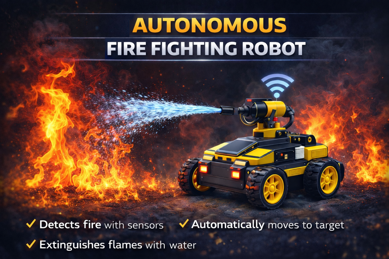
This project is an Autonomous Fire Fighting Robot designed to automatically detect and extinguish fire in small environments such as rooms, laboratories, warehouses, and industrial areas. The system is built using an Arduino Uno, flame sensors, DC motors, a servo motor, and a water pump mechanism.

The robot continuously monitors its surroundings using multiple flame sensors placed at different directions (left, right, and forward). When fire is detected, the robot automatically moves toward the flame source and activates the extinguishing system.

A servo motor rotates the water nozzle while the pump sprays water to suppress the fire. Once the fire is extinguished, the robot stops and resumes monitoring the environment.


βš™οΈ How It Works (Short & Simple)

πŸ”Ž Fire Detection

Three flame sensors detect fire in different directions:

β€’ Left sensor
β€’ Right sensor
β€’ Forward sensor

These sensors send signals to the Arduino Uno.


πŸ€– Robot Navigation

Two DC motors controlled through motor driver pins allow the robot to move:

β€’ Forward
β€’ Left
β€’ Right
β€’ Stop

The robot moves toward the detected flame direction.


🎯 Target Alignment

If the forward sensor detects fire, the robot moves straight toward the flame source.

If the left or right sensor detects fire, the robot turns in that direction.


πŸ’§ Fire Extinguishing System

Once the robot reaches the fire source:

β€’ The water pump activates.
β€’ The servo motor rotates the nozzle.
β€’ Water is sprayed across the flame area.

This sweeping motion increases the extinguishing coverage.


πŸ›‘ Fire Suppression Complete

When the fire is extinguished:

β€’ The pump turns OFF
β€’ The servo returns to center position
β€’ The robot stops and resumes monitoring


πŸ› οΈ Hardware Used

β€’ Arduino Uno
β€’ Flame Sensors (3x)
β€’ Servo Motor
β€’ Water Pump
β€’ DC Gear Motors (2x)
β€’ Motor Driver Module
β€’ Robot Chassis with wheels
β€’ Battery Power Supply
β€’ Jumper Wires
β€’ Water Tank


✨ Key Features

βœ” Automatic fire detection system
βœ” Autonomous robot navigation
βœ” Multi-direction flame sensing
βœ” Servo-controlled water spray nozzle
βœ” Automatic water pump activation
βœ” Compact robotic fire suppression system
βœ” Low-cost safety robotics project
βœ” Continuous environmental monitoring


πŸ“ˆ Applications

β€’ Industrial fire safety systems
β€’ Warehouse fire monitoring
β€’ Laboratory safety robots
β€’ Home fire detection prototypes
β€’ Robotics and automation research
β€’ Educational robotics projects
β€’ Smart building safety systems


πŸš€ Future Scope

β€’ Add ESP32-CAM for live fire monitoring
β€’ IoT-based fire alert system
β€’ GSM notification system for emergencies
β€’ Autonomous indoor navigation using sensors
β€’ Smoke and gas detection integration
β€’ Fire alarm integration with smart systems


πŸ‘ Advantages

β€’ Rapid fire detection and response
β€’ Reduces human risk during fire incidents
β€’ Automatic extinguishing system
β€’ Low-cost robotic safety solution
β€’ Portable and lightweight design
β€’ Easy to upgrade with IoT technologies


⚠️ Precautions

β€’ Ensure proper insulation for water pump wiring
β€’ Use stable battery power for motors and pump
β€’ Keep electronic components protected from water leakage
β€’ Regularly test flame sensors for accuracy
β€’ Avoid using near high-voltage equipment
β€’ Ensure water tank is filled before operation

πŸ“· ESP32-CAM Remote Controlled Robot Car


πŸ” Project Overview

This project uses an ESP32-CAM module to build a Wi-Fi controlled robot car with live video streaming and real-time motor control. The robot can be operated from a mobile browser over Wi-Fi while transmitting live camera feed.

The system runs independently using the ESP32’s built-in Wi-Fi β€” no external microcontroller required. It is suitable for surveillance, robotics learning, and IoT-based automation projects.


βš™οΈ How It Works (Short & Simple)

Camera streams live video
The ESP32-CAM captures and streams video over Wi-Fi through a web server hosted on the board.

Mobile connects via Wi-Fi
User connects to the ESP32’s IP address using a smartphone browser.

Motor driver controls movement
A motor driver module (like L298N or L293D) receives GPIO signals from ESP32 to control direction:

  • Forward
  • Backward
  • Left
  • Right
  • Stop

Real-time monitoring
User sees live camera feed while controlling the robot.

Standalone system
No cloud dependency β€” works on local Wi-Fi network.


πŸ› οΈ Hardware Used

  • ESP32-CAM
  • L298N / L293D Motor Driver Module
  • 4WD Robot Chassis
  • DC Gear Motors
  • Li-ion Battery Pack (7.4V recommended)
  • FTDI Programmer (for uploading code)
  • Jumper Wires
  • Power switch

✨ Key Features

βœ” Live Wi-Fi video streaming
βœ” Real-time remote control via mobile
βœ” No external microcontroller required
βœ” Built-in camera module
βœ” Lightweight and low-cost solution
βœ” Runs fully on ESP32
βœ” Suitable for IoT & robotics projects
βœ” Easy web-based interface


πŸ“ˆ Applications

Home surveillance robot
College robotics demonstration
Industrial inspection robot
Smart security vehicle
Warehouse monitoring
Research & AI experimentation
Remote controlled educational robot
Disaster area inspection prototype


πŸš€ Future Scope

AI object detection integration
Face recognition system
Two-way audio communication
Cloud video storage
Mobile app interface (Flutter / Android)
Night vision IR camera integration
Obstacle avoidance using ultrasonic sensor
GPS tracking system


πŸ‘ Advantages

Low-cost hardware
Compact design
Wireless operation
Portable system
Real-time monitoring
Easy to modify and upgrade
Good for beginners & advanced learners


⚠️ Precautions

Use proper 5V regulated power supply
Do not power motors directly from ESP32
Ensure stable Wi-Fi signal
Avoid overheating (add small heat sink if needed)
Secure wiring properly to prevent short circuit
Upload code carefully using correct boot mode

The Arduino Explorer: Smart Obstacle-Avoiding RobotΒ 

πŸ” Project Overview

The Arduino Explorer is an intelligent robotic car powered by the versatile Arduino Uno R3. It autonomously navigates its environment using smart sensor technology to detect and avoid obstacles. This project is ideal for beginners and enthusiasts stepping into robotics, programming, and automation with Arduino.


βš™οΈ How It Works (Short & Simple)

β€’ Sensing (The Eyes)
The HC-SR04 Ultrasonic Sensor, mounted on a servo motor, continuously emits sound waves and measures the time for them to return, acting as the robot’s eyes.

β€’ Scanning
The SG90 / MG90S Servo Motor pivots the sensor left and right, giving the robot a wide field of view to identify the clearest path.

β€’ Decision Making (The Brain)
The Arduino Uno processes distance data from the sensor. If an obstacle is detected, it decides whether to stop, reverse, or turn, ensuring safe navigation.

β€’ Action (The Movement)
Commands from the Arduino drive the L298N Motor Driver Module, which directs power from the 12V battery pack to the four DC motors, allowing the robot to move and avoid obstacles efficiently.


✨ Key Features

βœ” Arduino Uno-powered, beginner-friendly platform
βœ” Intelligent obstacle avoidance
βœ” Active scanning system via servo-mounted ultrasonic sensor
βœ” Four-wheel drive for excellent traction and maneuverability
βœ” Fully autonomous navigation


πŸ› οΈ Core Components

β€’ Brain: Arduino Uno R3
β€’ Chassis: 4-Wheel Robot Platform
β€’ Propulsion: 4 x DC Motors
β€’ Motor Control: L298N Motor Driver Module
β€’ Primary Sensor: HC-SR04 Ultrasonic Sensor
β€’ Scanning Mechanism: SG90 / MG90S Servo Motor
β€’ Power: 1 x 12V Battery Pack


πŸ“ˆ Applications

β€’ Beginner robotics learning
β€’ Obstacle avoidance practice
β€’ Autonomous vehicle prototypes
β€’ STEM education and DIY projects
β€’ Indoor navigation experiments


πŸš€ Future Scope

β€’ Add line-following functionality
β€’ Integrate Bluetooth or Wi-Fi control
β€’ Add camera for visual navigation
β€’ Implement path planning algorithms
β€’ Obstacle data logging and analytics


πŸ‘ Advantages

βœ” Easy to program and customize
βœ” Fully autonomous obstacle avoidance
βœ” Compact, low-cost hardware
βœ” Scalable for more sensors and features


⚠️ Precautions

β€’ Ensure proper battery voltage and wiring
β€’ Securely mount the sensor and servo
β€’ Avoid exposing electronics to water or dust
β€’ Test in a clear area to prevent damage

Search for products

Back to Top

Product Enquiry

Product has been added to your cart
Compare (0)